Views: 303
Altium Designer my Libraries, Project templates, System settings by Catcatcat. V26.0
Here I want to share how I configure Altium Designer and how I use the DXPPreferences1.DXPPrf files to quickly configure and get all the necessary tools for work, as well as for efficiently transferring these settings and databases between PCs.
When I started for me, there was a problem how to configure Altium, how to connect the database where to get the components, so that I could quickly start working and get the result. I want to offer a mechanism that will allow, after installing Altium Designer, to get a immediately configured database of components, a project structure that makes it possible to order printed circuit boards at least on JLCPCB, including, if desired, the assembly of the printed circuit board. In the structure you will find two examples of the project for which you can understand how the output files are formed, why they are needed and test the order of these boards for JLCPCB.
After using this Altium Designer customization engine, you will naturally get a system configured “for me”, but if there is further interest, I can describe how to redo everything so that you can have your own designs with your logos and your personal characteristics.
The entire configuration mechanism is contained in the archive Project.rar which you need to download and unzip the archive to the root of the C drive. This archive stores the entire project structure, all configuration data and the database of components with database projects.
For convenience, I recommend the following installation sequence, although you can perform all the settings on an already installed Altium. But I recommend installing an Altium “from scratch”.
The procedure for installing the Altium “from scratch”.
- Unzip the Project.rar archive to the root of drive D.
- Install four fonts from the folder D:\Project\Project_Altium\CH_Library\_Design\_Fonts_for_Altium\_Install fonts\ISOCPEUR by Catcatcat
- – ISOCPEUR-Bold.ttf
- – ISOCPEUR-Bold-Italic.ttf
- – ISOCPEUR-Italic.ttf
- – ISOCPEUR-Regular.ttf
- Install font from folder D:\Project\Project_Altium\CH_Library\_Design\_Fonts_for_Altium\_Install fonts
- – Mooretronics.ttf
this must be done!
- Install – Altium Designer.
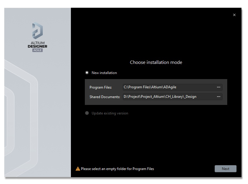
- When installing Altium, I recommend changing the path for the Shared Documents directory: to the folder D:\Project\Project_Altium\CH_Library\_Design\AD25 (This is not necessary, but it will give you an advantage in your job in the future.).
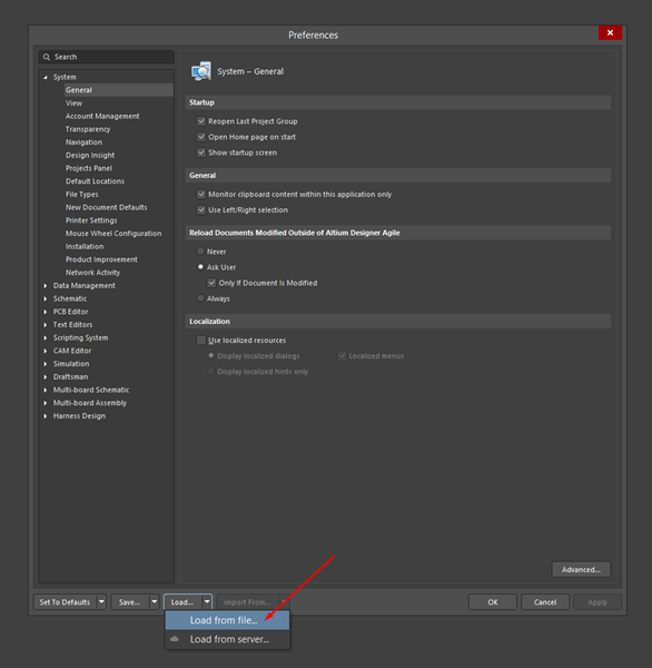
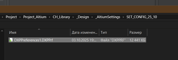
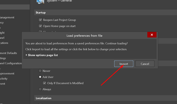
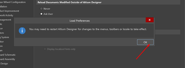
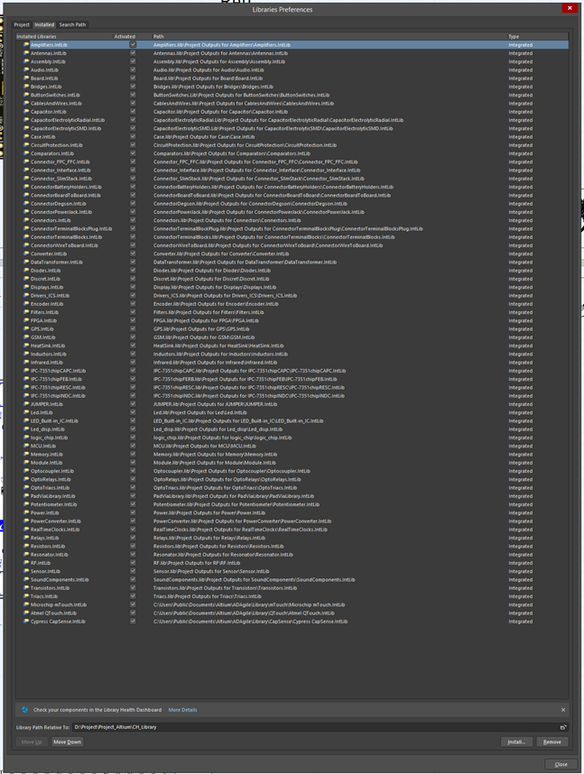
- After installing Altium and activating the license correctly, you need to reconfigure the settings using the file DXPPrf from the folder D:\Project\Project_Altium\CH_Library\_Design\_AltiumSettings\SET_CONFIG_25_10. After that, you need to restart Altium.
After that, you will get a fully configured system with a database of components, with a template of configured projects and working examples.
Development of electronics catcatcat.electronics@gmail.com
UA
Тут я хочу поділитися тим, як я налаштовую Altium Designer і як я використовую файли DXPPreferences1.DXPPrf для швидкого налаштування та отримання всіх необхідних інструментів для роботи, а також для ефективного перенесення цих налаштувань і баз даних між ПК.
Коли я починав, для мене виникла проблема, як налаштувати Altium, як підключити базу даних, де взяти компоненти, щоб я міг швидко почати працювати і отримати результат. Хочу запропонувати механізм, який дозволить після встановлення Altium Designer отримати одразу налаштовану базу компонентів, структуру проекту, яка дає можливість замовити друковані плати хоча б на JLCPCB, включаючи, за бажанням, збірку друкована плата. У структурі ви знайдете два приклади проекту, для яких ви можете зрозуміти, як формуються вихідні файли, навіщо вони потрібні та протестувати порядок цих плат для JLCPCB.
Після використання цього механізму налаштування Altium Designer ви, природно, отримаєте систему, налаштовану «для мене», але якщо виникне додатковий інтерес, я можу описати, як все переробити, щоб ви могли мати власні проекти з вашими логотипами та особистими характеристиками.
Весь механізм конфігурації міститься в архіві Project.rar, який потрібно завантажити та розархівувати в корінь диска D. У цьому архіві зберігається вся структура проекту, усі конфігураційні дані та база даних компонентів із проектами бази даних.
Для зручності я рекомендую наступну послідовність встановлення, хоча ви можете виконати всі налаштування на вже встановленому Altium. Але я рекомендую встановити Altium «з нуля».
Процедура установки Altium «з нуля».
- Розархівуйте в корінь диска D архів rar.
- Встановіть три шрифти з папки D:\Project\Project_Altium\CH_Library\_Design\_Fonts_for_Altium\_Install fonts\ISOCPEUR by Catcatcat
- – ISOCPEUR-Bold.ttf
- – ISOCPEUR-Bold-Italic.ttf
- – ISOCPEUR-Italic.ttf
- – ISOCPEUR-Regular.ttf
- Встановіть три шрифти з папки D:\Project\Project_Altium\CH_Library\_Design\_Fonts_for_Altium\_Install fonts
- – Mooretronics.ttf
це треба зробити обов’язково!
- Встановіть Altium Designer.
- Під час інсталяції Altium я рекомендую змінити шлях для каталогу Shared Documents: до папки D:\Project\Project_Altium\CH_Library\_Design\AD25 (це не обов’язково, але в майбутньому це дасть вам перевагу в Ваша робота).
- Після інсталяції Altium і правильної активації ліцензії вам потрібно повторно налаштувати параметри за допомогою файлу DXPPrf з папки D:\Project\Project_Altium\CH_Library\_Design\_AltiumSettings\SET_CONFIG_25_10. Після цього потрібно перезапустити Altium.
Після цього ви отримаєте повністю налаштовану систему з базою даних компонентів, з шаблоном налаштованих проектів і робочими прикладами.
Зверніть увагу на символи в дужках у компонентах десигнаторів.
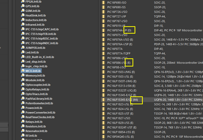
JLCPCB
(E) – Extended Part,
(B) – Basic Part,
Digikey
(D)
Mouser
(M)
TME
(T)
Microchip
(Mi)
Це інформація розробнику про постачальника компонента, що використовується.
Розробка електроніки catcatcat.electronics@gmail.com
AD installation.
- Installing Altium
- Adding a license.
Perform configuration for full operation of the work
Release updates
Comments and suggestions are welcome.
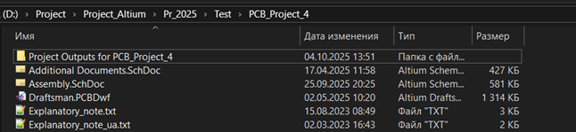
V. – 26 – recommended template
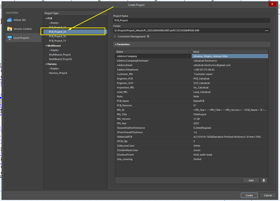
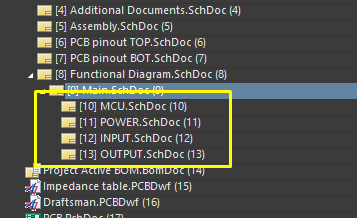
Project Template Structure:
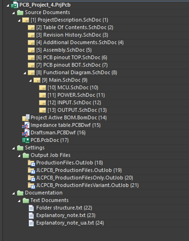
ProjectDescription.SchDoc – Brief description of the project
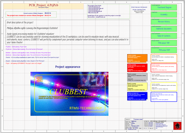
Table Of Contents.SchDoc – Brief description of the purpose of the project sheets.
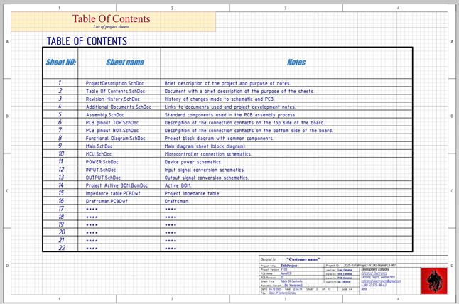
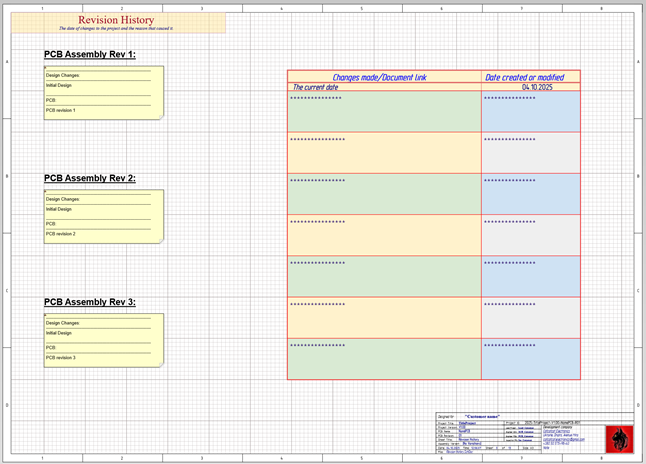
Revision History.SchDoc – Description of PCB design revisions.
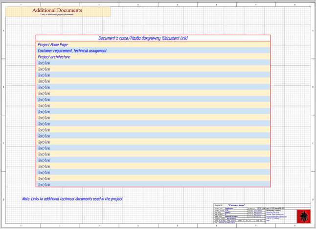
Additional Documents.SchDoc – Description and links to resources used in the project.
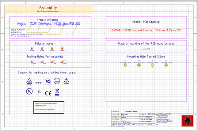
Assembly.SchDoc – Components used at the PCB assembly stage.
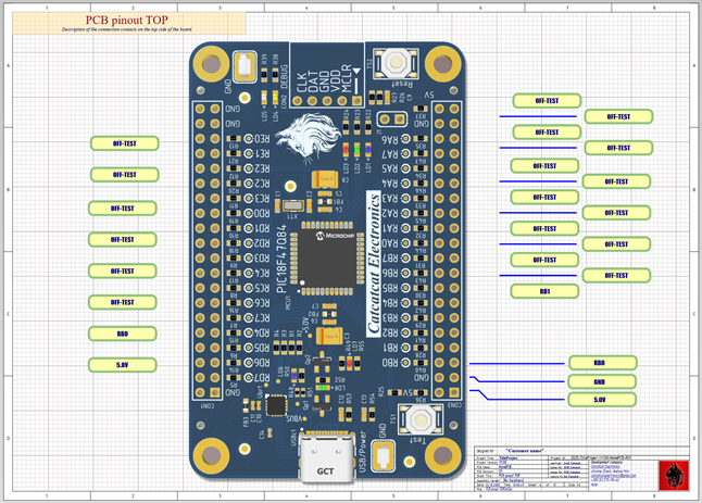
PCB pinout TOP.SchDoc (PCB pinout BOT.SchDoc) – Description of the printed circuit board interface (Example to get you started).
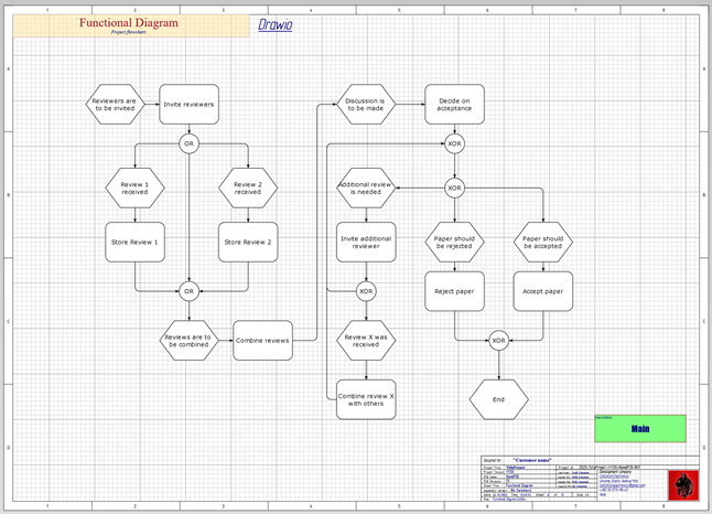
Functional Diagram.SchDoc – Functional diagram of the project, it is recommended to use Drawio for development.
Main.SchDoc – Main project sheet.
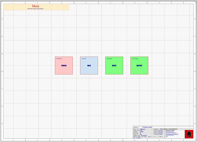
Project worksheets. Add and remove sheets here. However, it is recommended that each individual project task be completed on a separate sheet.
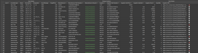
Project Active BOM.BomDoc – Here you can get information about the components used, their life cycle, current price and available quantity from the distributor.
Note: This feature is not available to all distributors and does not work with LCSC.
Example of work:
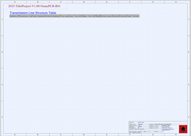
Impedance table.PCBDwf – This sheet will generate a report on the structure of the conductor impedances used.
Draftsman.PCBDwf – Additional visual information on PCB assembly (The example is taken from the demo project).
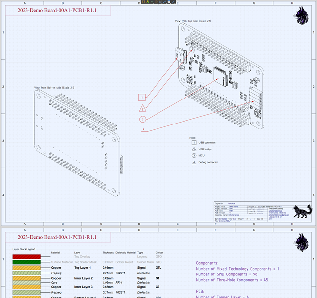
PCB.PcbDoc – A sheet template to start designing a printed circuit board.
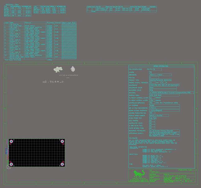
By default, a 10-layer stack is loaded. Additional stacks can be loaded from the folder D:\Project\Project_Altium\CH_Library\_Design\Stackup Use stacks from the last year.
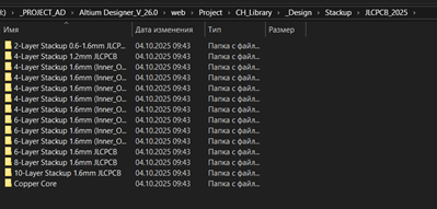
These stacks are taken from the manufacturer JLCPCB.
If you plan to have your printed circuit boards manufactured at another facility, contact the PCB manufacturer for information on the materials used. This will save you unnecessary hassle during production.
Preparation of documentation for the production of printed circuit boards.
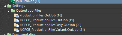
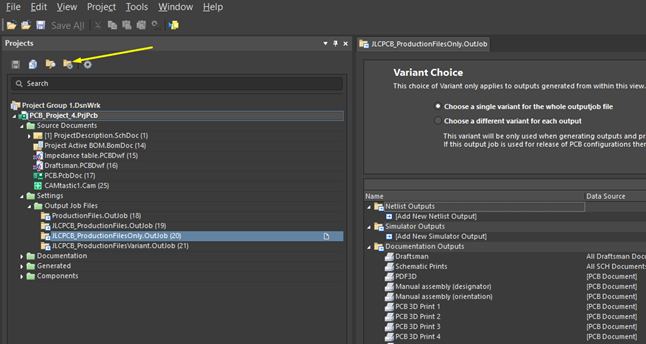
ProductionFiles.OutJob – Here you will find a complete list of generated documents suitable for any type of printed circuit board manufacturing, as well as obtaining a variety of documentation necessary for professional production.
Manufacturer-focused documents jlcpcb.
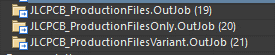
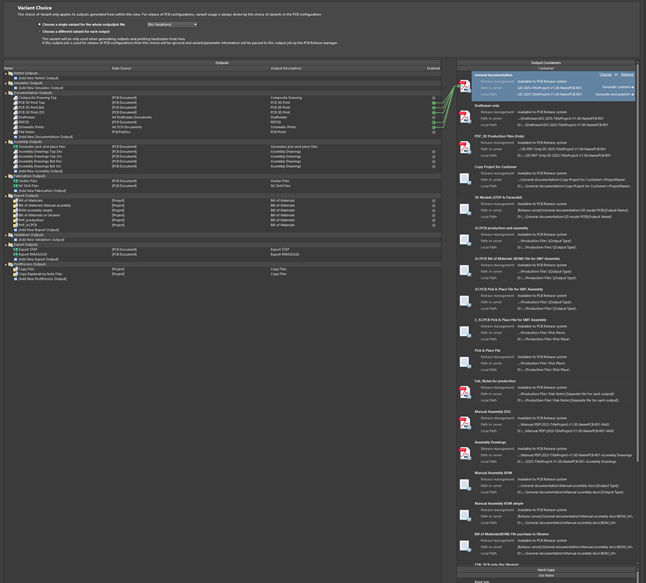
JLCPCB_ProductionFilesOnly.OutJob – The recommended option for optimal development of documentation for the manufacture and assembly of printed circuit boards.
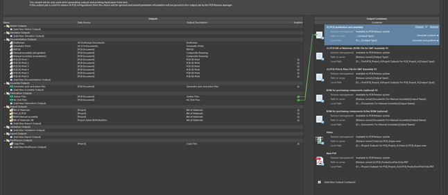
JLCPCB production and assembly – Obtaining Gerber files.
JLCPCB Bill of Materials (BOM) File for SMT Assembly V2 – Obtaining a specification file in JLCPCB format *
JLCPCB Pick & Place File for SMT Assembly V2 – Getting a Pick & Place file in JLCPCB format *
P.s. * – Additional processing is required to remove unnecessary columns and rows.
BOM for purchasing components (optional) V2 – BOM file for purchasing components if manual assembly is expected.
You will find the generated production files inside the project folder named (example) Project Outputs for PCB_Project_4.
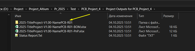
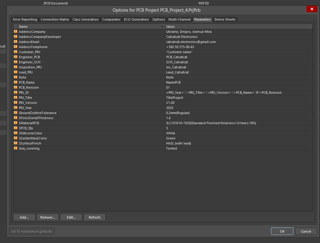
Please note that the project file name changes in the project properties.
Change these parameters to suit your needs and the file names will be automatically changed when generating production documentation.
The Status Report.Txt files can be deleted; the manufacturer doesn’t need them.
The 2025-TitleProject-V1.00-NamePCB-R01 folder can be added to the archive.
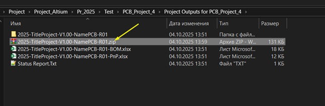
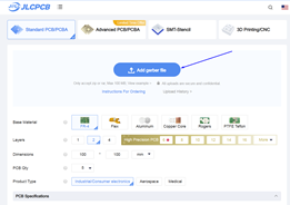
This archive can also be uploaded to JLCPCB for PCB fabrication.
Use the *BOM.xlsx and *PnP.xlsx files if you need PCB assembly at this factory.
Database structure:
Enjoy, design, make, be the first!
Catcatcat!
Download the library.
Altium Designer my Libraries, Project templates, System settings by Catcatcat. V26.0 8 МБ 114 downloads
Here I want to share how I configure Altium Designer and how I use the DXPPreferences1.DXPPrf...Це може бути цікаво!
 LCD драйвер – UC1601sViews: 1836 http://svetomuzyka.narod.ru/project/UC1601s.html Читайте обновление на http://catcatcat.d-lan.dp.ua/?page_id=178 В данный момент можно приобрести в ООО “Гамма” несколько типов индикаторов на драйвере UC1601s. RDX0048-GC, RDX0077-GS, RDX0154-GC и RDX0120-GC выполнены по технологии COG.
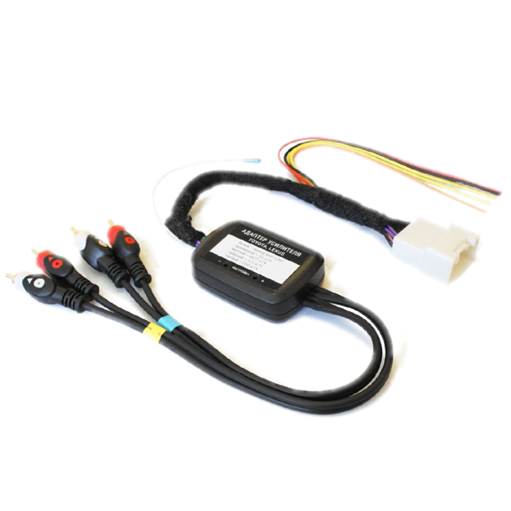 Toyota Auto Fader – Модуль включения усилителяViews: 2126 Toyota Auto Fader – Модуль включения усилителя. Часто автолюбители прибегают к замене штатного головного устройства на универсальное мультимедийное, в котором значительно расширены функциональные возможности. Если возникает желание оставить …
 PIC32MZ – прерывания (заметки)Views: 536 Виды формирования запоминая контекста при входе в прерывания. Компилятор представляет три варианта AUTO – когда запоминания места возврата из подпрограммы возложено на программу, т.е все создается программно. Этот …
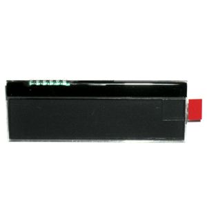 LCD индикаторы на драйвере ML1001Views: 2063 ML1001 – статический LCD GOG (чип в стекле) драйвер для 40-сегментного LCD в позолоченном противоударном исполнении. На них можно каскадно строить цельные из 80 или 120 сегментов LCD индикаторы. …
 MPLAB X IDE – управление проектамиViews: 1211 Среда MPLAB X IDE позволяет оперативно работать с несколькими проектами, например, если у вас в работе несколько проектов: Для того чтобы переключиться достаточно выбрать другой проект: Для выбора …
 Самый простой индикатор уровня звукового сигналаViews: 6724 Демонстрационный проект создания индикаторов уровня с использованием WS2812B. Изучив этот проект вы сможете самостоятельно изготавливать и конструировать свои индикаторы уровня звукового сигнала. Дополнительно читайте статью Бегущие огни на …
 Altium Designer my Libraries, Project templates, System settings by Catcatcat V23.04Views: 468 Смотри как установить и подключить библиотеку тут. V. – 23_04 – Component Database Update. – configuration file name – DXPPreferences1.DXPPrf. – Added two projects for audio amplifier …
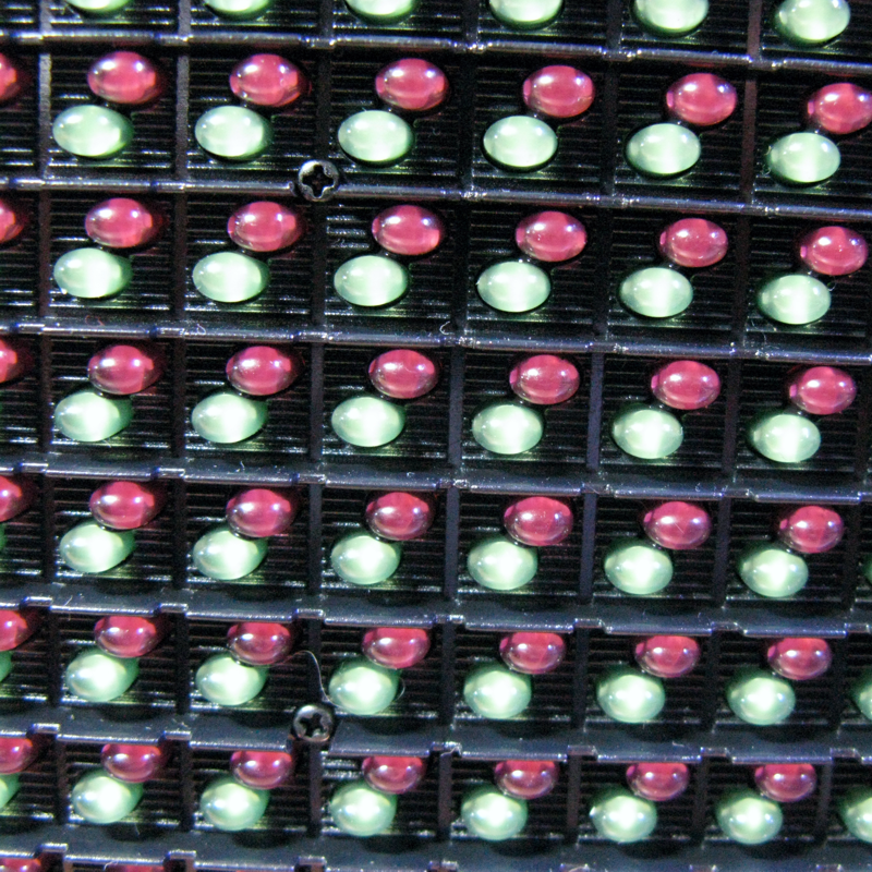 LED модуль P10C4V12Views: 3324 LED панели на обычных регистрах типа 74HC595. Они выпускаются как монохромные так двух и полно цветные, особенность, что они предназначены для текстовой информации и имеют один уровень яркости. Общую яркость …
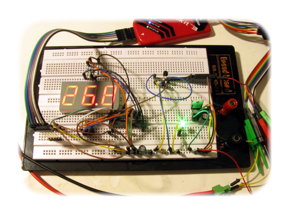 Индикатор температурыViews: 2855 Проект для начинающих, на демо плате BB-2T3D-01. Простой индикатор температуры. Проект никак не задумывался, просто на витрину магазин Ворон нужна была демонстрационная модель на макетной плате, чего нибудь работающего. Остановились на индикаторе …
 Customs codes for exportViews: 385 Митні коди (HS Code) для надсилання посилок за кордон. Для відправки товару за кордон на сьогодні необхідно зазначати митні коди. Часто визначення коду займає багато часу. Для …
Комментарии