Views: 690
Author li grey
email: greyli1987@outlook.com

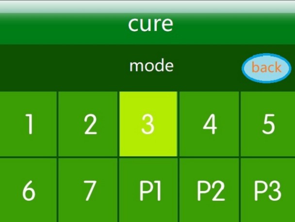
The strain assessment instrument is used to assess the degree of corresponding muscle strain by obtaining the muscle surface action potential through silver oxide electrodes or other human surface electrodes, together with the patient’s conscious control of muscle movements. The highest level of muscle strain is 7 and the lowest level is 1. Level 1 is a mild condition, followed by levels 2, 3, 4 and 5, and levels 6 and 7 are severe conditions. This project uses the STONE serial touch screen animation to display the evaluation process, and the end of the evaluation will give the level of the proposed treatment plan display. The accessories are as follows.
- Arduino EMG feedback module.
- STVI056WT-01 serial touch screen and STONE adapter board V1.2.
- Electrodes, electrode wires.
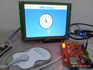
The main interface is as follows.
The return value of the main interface button “start” is 0061. The storage address is 0003. This button will start the EMG measurement, during the measurement, the patient should exert force on the muscle at the electrode, and gradually increase the force until it reaches his maximum strength, then try to hold it for a period of time, then slowly relax, relax, until it is completely relaxed. The internal algorithm of Arduino will give the result of muscle strain and the corresponding treatment plan number according to the strength, duration and change of the measured EMG signal.

Working idea.
Serial screen carries evaluation animation, real-time clock display, output results (and treatment plan number), arduino development board completes EMG signal acquisition and analysis, arduino development board also controls EMG acquisition channel electronic switch (electronic switch action also has LED indication), responding to user operation.
Working steps.
- Build hardware.
- connect electrode wires and electrode pads.
- connect STONE touch screen and arduino development acquisition board.
- connect the power supply.
- Evaluate the animation chart into STONE screen development platform Tool4.3; make pointer clock.
- Connect the touch screen and arduino development board via serial port, program the evaluation animation and evaluation algorithm, and upload the evaluation results to the touch screen for display.
Next, record the specific development process.
First, build the hardware connection.
Connect the components well according to the working steps, as follows.

Next, the evaluation animation and output result images were created.
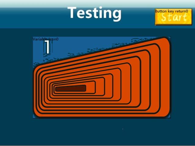
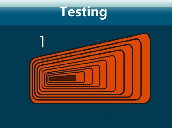
The 451*268 evaluation animation icons created according to the resolution of the STONE screen used in this project are as follows.
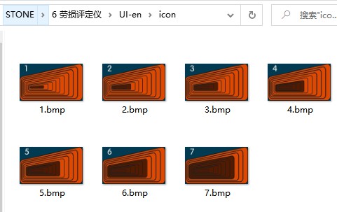
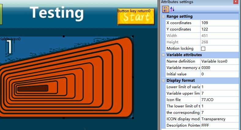
The instructions for calling each icon based on the variable icon address and picture location number are as follows.
A5 5A 05 82 03 00 00 01 (Call icon 1)

A5 5A 05 82 03 00 00 02 (Call icon 2)

......

A5 5A 05 82 03 00 00 07 (Call icon 7)


After the evaluation, the output page jump instruction is

A5 5A 04 80 03 00 01 (Jump to page 1)

A5 5A 04 80 03 00 02 (Jump to page 2)

......

A5 5A 04 80 03 00 07 (Jump to page 7)
Note: The animation shows the EMG measurement process, if you use the left negative, the value change will leave a shadow of “1”. Please use the right negative correctly.

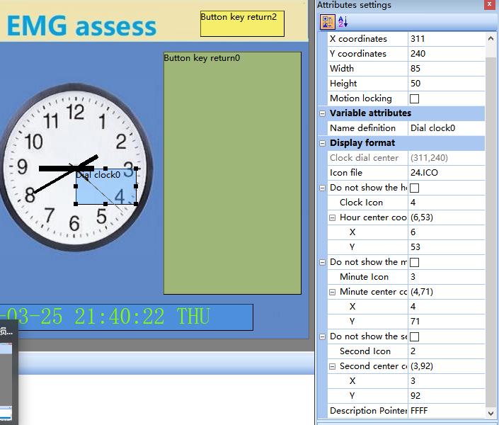
Creation of a pointer-type real time clock.
Select Dial clock control under menu Variable Configuration (D) and create it in the center of the dial (the upper left corner of the formed rectangle automatically becomes the rotation axis of the hands —- which is the “clock dial center” in the parameter table). The hour, minute and second hand icons are in 24.ico, select them in the Icon file, where the serial number of the hour hand icon is “4”, the serial number of the minute hand icon is “3”, and the serial number of the second hand icon is “2 “, respectively, corresponding to the selected. Next, you need to determine the hour hand, minute hand, second hand “axis”, where the Y axis is the length of each needle out (also equivalent to the center of the two sides of the distribution ratio), relatively easy to adjust, while the X axis is the focus, the three needles rotate when the intersection of whether to coincide, depending on the value of this. Of course, you need to watch them rotate for a while, and if they do not overlap, adjust a little until you are satisfied.
Finally, programming and debugging.
This project uses the arduino development board programming. (arduino development board, model is LY-F2)
With the above introduction, the arduino code is as follows.
//EMG assess is testing for people.
// by Frank 20210326.
//
#include <Servo.h>
int pos = 0;    // variable to store the servo position
int inDelay = 0;
String inString = "";    // String buffer
// Pin 13 has an LED connected on most Arduino boards.
// give it a name:
int led = 13;       // in pcba
int led2 = 12;       // yellow
int led3 = 11;       // red
int ipage = 1;         //  Pointer buffer 1-7
int ipage0;            //  Pointer buffer 1-7
int ipage2;            //  Pointer buffer 1-7
int biaozhi = 0;  // 1 = begin, 0 = stop.
int threeok;      // 3 = trun to reslut page  and biaozhi zero,
int dataMuscle = 0;   // The muscle data of testing.
void setup()
{
   pinMode(led, OUTPUT);        // initialize the digital pin as an output.
  pinMode(led2, OUTPUT);        // initialize the digital pin as an output.
  pinMode(led3, OUTPUT);        // initialize the digital pin as an output.
  Serial.begin(9600);  // Open the serial communication function and wait for the serial port to open
  while (!Serial) {
    ; // wait for serial port to connect. Needed for Leonardo only
  }
}
void loop()
{
  int inChar;
  if(inDelay == 0){
       inDelay = 1;                //RTC is only once!
      //-------------------------RTC--------------------------
        Serial.write(0xA5);       //"A5" is 165
        Serial.write(0x5A);       //"5A" is 90
        Serial.write(0x0A);
        Serial.write(0x80);
        Serial.write(0x1F);
        Serial.write(0x5A);
        Serial.write(0x21);
        Serial.write(0x03);
        Serial.write(0x26);            // 3 month 26 day
        Serial.write(0x05);            // friday
        Serial.write(0x11);
        Serial.write(0x08);
        Serial.write(0x57);           // 11:08:57
      //---------------------------------------------------
  }
  // 读取串口发送的信息:Read the information sent by the serial port:
  if (Serial.available() > 0)   {    inChar = Serial.read();  }
  /* begin key is biaozhi = 1 ! */
  if ((inChar == 0x61)&&(biaozhi == 0)) {        // 0x0061 is the begin key !
     biaozhi = 1;
     threeok = 0;
     dataMuscle = random(1,7);            //shui ji shu (1-7)   ,it is the result num!
     ipage2 = 0;
     ipage3 = 0;
  }
  /*-------------------------------------EMG assess begin------------------------------*/
  if(biaozhi == 1)     // begin EMG assess testing!
  {
     digitalWrite(led, HIGH);   // turn the LED on (HIGH is the voltage level)
    //------------------------------------------1------------------------------------------
     if (ipage < 7)            // only begin look each page!
     {
         for(ipage0 = ipage; ipage0 < 7; ipage0 += 1)      // Num 1+
        {
              // variable Icon + 1
            Serial.write(0xA5);       //"A5" is 165
            Serial.write(0x5A);       //"5A" is 90
            Serial.write(0x05);
            Serial.write(0x82);
            Serial.write(0x03);
            Serial.write(0x00);
            Serial.write(0x00);
            Serial.write(ipage0);    // 0-7 page all can look!
            delay(600);              // waits 0.6s
            if((ipage0 == (dataMuscle + 1))&&(ipage2 == 0)){
              ipage2 = 1;
              ipage0 -= 2;
            }
        }
        ipage = 7;
        ipage2 = 0;
        digitalWrite(led3, HIGH);   // turn the LED on (HIGH is the voltage level)
        for(ipage0 = ipage; ipage0 > 0; ipage0 -= 1)  // Num 1-
        {
          Serial.write(0xA5);       //"A5" is 165
          Serial.write(0x5A);       //"5A" is 90
          Serial.write(0x05);
          Serial.write(0x82);
          Serial.write(0x03);
          Serial.write(0x00);
          Serial.write(0x00);
          Serial.write(ipage0);    // 01-7 page all can look!
          delay(900);              // waits 0.9s
          if((ipage0 == (dataMuscle - 1))&&(ipage2 == 0)){
              ipage2 = 1;
              ipage0 += 2;
          }
        }
        ipage = 1;
        ipage2 = 0;
   }
    threeok = 1;
    //----------------------------------------2------------------------------------------
       digitalWrite(led, LOW);    // turn the LED off by making the voltage LOW
     digitalWrite(led2, HIGH);    // turn the LED off by making the voltage LOW
     digitalWrite(led3, LOW);    // turn the LED off by making the voltage LOW
       if (ipage < 7)            // only begin look each page!
   {
     for(ipage0 = ipage; ipage0 < 7; ipage0 += 1)      // Num 1+
      {
              // variable Icon + 1
        Serial.write(0xA5);       //"A5" is 165
        Serial.write(0x5A);       //"5A" is 90
        Serial.write(0x05);
        Serial.write(0x82);
        Serial.write(0x03);
        Serial.write(0x00);
        Serial.write(0x00);
        Serial.write(ipage0);    // 1-7 page all can look!
        delay(500);              // waits 0.6s
        if((ipage0 == (dataMuscle + 1))&&(ipage2 == 0)){
           ipage2 = 1;
           ipage0 -= 2;
         }
      }
      ipage = 7;
      ipage2 = 0;
      digitalWrite(led3, HIGH);   // turn the LED on (HIGH is the voltage level)
      for(ipage0 = ipage; ipage0 > 0; ipage0 -= 1)  // Num 1-
      {
        Serial.write(0xA5);       //"A5" is 165
        Serial.write(0x5A);       //"5A" is 90
        Serial.write(0x05);
        Serial.write(0x82);
        Serial.write(0x03);
        Serial.write(0x00);
        Serial.write(0x00);
        Serial.write(ipage0);    // 0-7 page all can look!
        delay(800);              // waits 0.9s
        if((ipage0 == (dataMuscle - 1))&&(ipage2 == 0)){
            ipage2 = 1;
            ipage0 += 2;
        }
      }
      ipage = 1;
      ipage2 = 0;
   }
    threeok = 2;
    //------------------------------------------3------------------------------------------
        digitalWrite(led, LOW);    // turn the LED off by making the voltage LOW
     digitalWrite(led2, LOW);    // turn the LED off by making the voltage LOW
     digitalWrite(led3, HIGH);    // turn the LED off by making the voltage LOW
   if (ipage < 7)            // only begin look each page!
   {
     for(ipage0 = ipage; ipage0 < 7; ipage0 += 1)      // Num 1+
      {
              // variable Icon + 1
        Serial.write(0xA5);       //"A5" is 165
        Serial.write(0x5A);       //"5A" is 90
        Serial.write(0x05);
        Serial.write(0x82);
        Serial.write(0x03);
        Serial.write(0x00);
        Serial.write(0x00);
        Serial.write(ipage0);    // 0-7 page all can look!
        delay(300);              // waits 0.6s
        if((ipage0 == (dataMuscle + 1))&&(ipage2 == 0)){
            ipage2 = 1;
            ipage0 -= 2;
        }
      }
      ipage = 7;
      ipage2 = 0;
      digitalWrite(led, HIGH);   // turn the LED on (HIGH is the voltage level)
      for(ipage0 = ipage; ipage0 > 0; ipage0 -= 1)  // Num 1-
      {
        Serial.write(0xA5);       //"A5" is 165
        Serial.write(0x5A);       //"5A" is 90
        Serial.write(0x05);
        Serial.write(0x82);
        Serial.write(0x03);
        Serial.write(0x00);
        Serial.write(0x00);
        Serial.write(ipage0);    // 0-7 page all can look!
        delay(600);              // waits 0.9s
        if((ipage0 == (dataMuscle - 1))&&(ipage2 == 0)){
            ipage2 = 1;
            ipage0 += 2;
        }
      }
      ipage = 1;
      ipage2 = 0;
   }
   threeok = 3;
  }// end if(biaozhi == 1)
  /*-------------------------------------EMG assess  END -----------------------------*/

  if(threeok == 3)      // 3 = trun to reslut page  and biaozhi zero,
  {
    biaozhi = 0;
    threeok = 0;
    //trun reslut page.
        Serial.write(0xA5);       //"A5" is 165
        Serial.write(0x5A);       //"5A" is 90
        Serial.write(0x04);
        Serial.write(0x80);
        Serial.write(0x03);
        Serial.write(0x00);
        Serial.write(dataMuscle);
     digitalWrite(led, LOW);    // turn the LED off by making the voltage LOW
     digitalWrite(led2, HIGH);    // turn the LED off by making the voltage LOW
     digitalWrite(led3, LOW);    // turn the LED off by making the voltage LOW
  }//end if(threeok == 3)
}
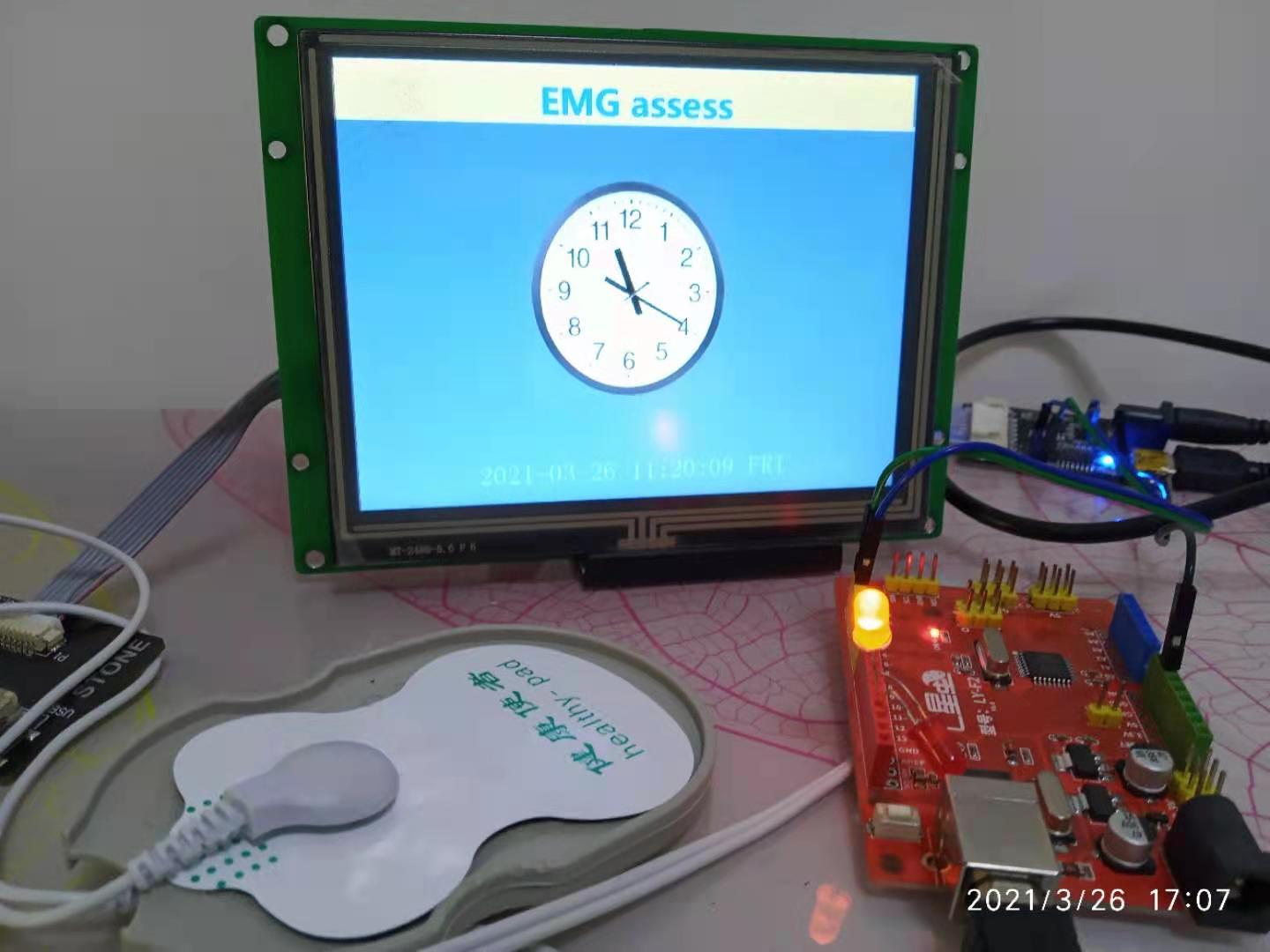
Finally, online commissioning.
STONE Tool software edited the screen file download, arduino code file upload, connect the power supply, communication, arduino development board connected to the electrode line, electrode piece, acquisition switch and acquisition module, operate the touch screen keys, observe the pointer type real-time clock, evaluation animation, output indication jump function are demonstrated normal!
Это может быть интересно
 Audio-bluetooth modules BK8000L (noname)Views: 899 Еще один вариант, так сказать недоразумения Audio-bluetooth modules BK8000L (noname). Его отличительной маркировкой служат два отверстия в плате и надпись R2. Отличают его от модулей на чипе BK8000L, …
 12-BIT A/D CONVERTER WITH THRESHOLD DETECT на примере PIC24FJ128GA204Views: 965 Введение. 12-битный модуль A/D Converter является усовершенствованной версией 10-битного модуля, предлагаемого на некоторых устройствах PIC24. Оба модуля являются преобразователями, в своих ядрах, с последовательным приближением (SAR), в окружении …
 Altium Designer my setup system and project structure V23.3Views: 459 Оновлення бази даних та шаблонів від березня 2023 року. Updating the database and templates from March 2023. Altium Designer my Libraries, Project templates, System settings by Catcatcat. Дивись …
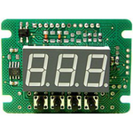 Универсальный терморегулятор ch-c3000Views: 3236 Терморегулятор ch-c3000 предназначен для управления системами регулирования температуры в пределах от – (минус) 55 до + 125 С. Регулятор может использоваться как в системах отопления, так и в …
 Простой сенсорный регулятор светаViews: 2518 Простой сенсорный регулятор. Проект – 2007 года. Регулятор выполнена на микроконтроллере PIC12F683 и имеет минимальное количество элементов. Выполняет стандартные функции, включение выключение света, изменение яркости, запоминание последнего установленного уровня …
 MPLAB X IDE – управление проектамиViews: 1211 Среда MPLAB X IDE позволяет оперативно работать с несколькими проектами, например, если у вас в работе несколько проектов: Для того чтобы переключиться достаточно выбрать другой проект: Для выбора …
 Electronic Speed Controller for FPV droneViews: 56 Другий проект цієї серії, це контролер швидкості або контролер управління BLCD мотором. Для аналізу було вибрано плату SpeedyBee BLS 55A 4-in-1 ESC із комплекту SpeedyBee F405 V4 BLS …
 Проект с использованием MCC часть 09Views: 1071 Эта часть будет посвящена созданию практического проекта управления освещение. Тех задание: Два выхода управления ШИМ – светодиодным освещением. Две кнопки управления, каждая кнопка управляет, своим каналом, логика самая …
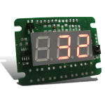 Индикатор кода – RC-5 Protocol PhilipsViews: 1187 Индикатор кода – RC-5 Protocol Philips При конструировании дистанционного управления на инфракрасных лучах для контроля удобно иметь индикатор кодов передаваемых пультом. Плата ch-c3000 позволяет изготавливать устройства с возможностью …
 Четырех канальный терморегулятор ch-4000Views: 3437 Четыре независимых канала регулирования температуры, одновременно можно подключить 16 датчиков температуры DS18B20 с удалением до трехсот метров. Можно для регулировки выбрать любой датчик, подключенный к устройству. Каждый канал может работать …
Комментарии